

NEWS
Energy Storage System Operational States and Control Logic
Release Time:
2025-03-04 18:14
Source:
MITSCN

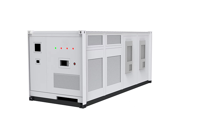
Energy Storage System Operational States and Control Logic
The operational states and control logic of an energy storage system are critical to ensuring its efficient, safe, and stable operation.
Taking a grid-connected energy storage system as an example, local control primarily handles system self-testing, device startup, PCS (Power Conversion System) power dispatch, alarm management, and fault protection. The workflow of the energy storage system is divided into :
7 main states:
1. Black Start
2. Power-On
3. Standby
4. Startup
5. Operation
6. Fault & Alarm
7. Shutdown
Black Start Phase:
- All internal equipment is in a shutdown state.
- Control power and main power supplies are disconnected.
Power-On Phase:
- The system achieves a "black start" using external power or an internal UPS (Uninterruptible Power Supply).
- The local controller coordinates self-testing across major internal devices and waits for the main power circuit to energize.
- Air conditioning and heating systems activate to create a suitable temperature environment for the batteries.
- Once conditions are met, the system enters **Standby** mode, awaiting EMS (Energy Management System) or upper-level startup commands.
Note: If using UPS power, operators must promptly connect the main power circuit to avoid UPS over-discharge or recharge the UPS via an external control power port.
Standby Phase:
- The system maintains suitable internal temperatures.
- Continuously monitors grid voltage, internal conditions, and device statuses.
Startup Phase:
- The local controller receives an external startup command and sequentially:
- Activates battery voltage output.
- Establishes and verifies DC circuit voltage.
- Configures PCS operating modes.
- Initiates PCS operation.
- Engages transformer soft-start circuits (if applicable).
- Reports startup status and data to the EMS.
Operation Phase:
- The local controller:
- Executes commands based on system operating modes.
- Monitors environmental conditions and system statuses.
- Collects, records, and uploads data.
- Manages human-machine interfaces.
- Adjusts PCS output power in real-time based on battery status and temperature.
- Coordinates power/current command corrections for parallel PCS groups (if applicable).
Fault & Alarm Phase:
- Faults are classified into three severity levels:
1. Alarm: Non-critical issues (e.g., single battery cluster shutdown, PCS overtemperature, transient SPD alerts).
- The system continues operating but notifies operators or reduces power temporarily.
- Alarms may escalate to **Fault I** if unresolved within a set timeframe.
2. Fault I: Severe issues (e.g., widespread battery cluster failures, critical insulation faults, cooling system failures).
- PCS power ramps down to shutdown.
- DC/AC circuits disconnect.
- Battery outputs open at zero current.
- Auxiliary systems (e.g., cooling, fire protection) remain active.
3. Fault II: Critical emergencies (e.g., fire).
- Immediate full shutdown (equipment and power circuits).
- Maintains temporary communication to transmit temperature/pressure data.
- System enters **Black Start** state.
Shutdown Phase:
- Two shutdown modes:
1. Shutdown I:
- PCS stops grid-connected output.
- Batteries remain connected to the PCS DC side for rapid restart.
2. Shutdown II:
- Full disconnection of PCS and batteries from AC/DC circuits.
- Auxiliary systems (cooling, fire protection) continue operating.
Control Logic for Large-Scale Systems:
- A local controller may manage **n independent subsystems** (each with dedicated PCS and batteries).
- Key responsibilities:
- Ensure total output meets EMS requirements.
- Allocate power between PCS units based on battery SOC (State of Charge).
Notes:
- Technical terms retained: PCS (Power Conversion System), EMS (Energy Management System), UPS (Uninterruptible Power Supply), SPD (Surge Protection Device).
Related News
MESSAGE
QUESTION TO MITSCN
Message
Service Tel:+86-10-64933458
Email:Sales@mitscn.com
Copyright © Beijing MITSCN Co., LTD All rights reserved